- 您现在的位置:买卖IC网 > Sheet目录3872 > PIC18F4450T-I/ML (Microchip Technology)IC PIC MCU FLASH 8KX16 44QFN
125
XMEGA A [MANUAL]
8077I–AVR–11/2012
12.
Interrupts and Programmable Multilevel Interrupt Controller
12.1
Features
Short and predictable interrupt response time
Separate interrupt configuration and vector address for each interrupt
Programmable multilevel interrupt controller
– Interrupt prioritizing according to level and vector address
– Three selectable interrupt levels for all interrupts: low, medium and high
– Selectable, round-robin priority scheme within low-level interrupts
– Non-maskable interrupts for critical functions
Interrupt vectors optionally placed in the application section or the boot loader section
12.2
Overview
Interrupts signal a change of state in peripherals, and this can be used to alter program execution. Peripherals can have
one or more interrupts, and all are individually enabled and configured. When an interrupt is enabled and configured, it
will generate an interrupt request when the interrupt condition is present. The programmable multilevel interrupt
controller (PMIC) controls the handling and prioritizing of interrupt requests. When an interrupt request is acknowledged
by the PMIC, the program counter is set to point to the interrupt vector, and the interrupt handler can be executed.
All peripherals can select between three different priority levels for their interrupts: low, medium, and high. Interrupts are
prioritized according to their level and their interrupt vector address. Medium-level interrupts will interrupt low-level
interrupt handlers. High-level interrupts will interrupt both medium- and low-level interrupt handlers. Within each level, the
interrupt priority is decided from the interrupt vector address, where the lowest interrupt vector address has the highest
interrupt priority. Low-level interrupts have an optional round-robin scheduling scheme to ensure that all interrupts are
serviced within a certain amount of time.
Non-maskable interrupts (NMI) are also supported, and can be used for system critical functions.
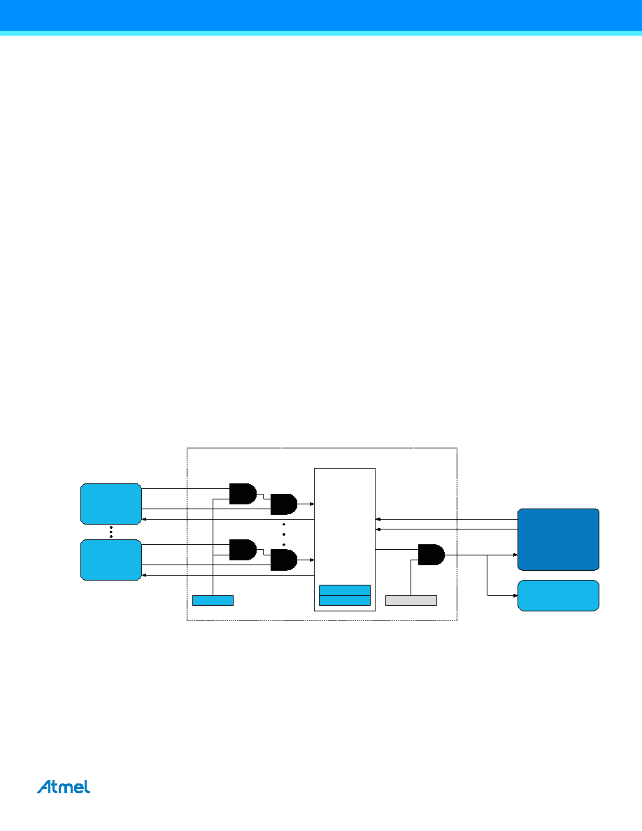
Figure 12-1. Interrupt controller overview
12.3
Operation
Interrupts must be globally enabled for any interrupts to be generated. This is done by setting the global interrupt enable
( I ) bit in the CPU status register. The I bit will not be cleared when an interrupt is acknowledged. Each interrupt level
must also be enabled before interrupts with the corresponding level can be generated.
When an interrupt is enabled and the interrupt condition is present, the PMIC will receive the interrupt request. Based on
the interrupt level and interrupt priority of any ongoing interrupts, the interrupt is either acknowledged or kept pending
until it has priority. When the interrupt request is acknowledged, the program counter is updated to point to the interrupt
Peripheral 1
Interrupt Controller
INT REQ
INT LEVEL
INT REQ
INT LEVEL
CPU INT REQ
CTRL
LEVEL Enable
CPU.SREG
Global
Interrupt
Enable
Priority
decoder
STATUS
INTPRI
INT ACK
Peripheral n
INT LEVEL
INT REQ
INT ACK
CPU
CPU INT ACK
CPU ”RETI”
Sleep
Controller
Wake-up
发布紧急采购,3分钟左右您将得到回复。
相关PDF资料
PIC18F4321T-I/ML
IC PIC MCU FLASH 4KX16 44QFN
PIC18F4221T-I/ML
IC PIC MCU FLASH 2KX16 44QFN
PIC18F2321T-I/ML
IC PIC MCU FLASH 4KX16 28QFN
PIC18F2221T-I/SO
IC PIC MCU FLASH 2KX16 28SOIC
PIC16LF1939-I/MV
IC MCU 8BIT 28KB FLASH 40-UQFN
PIC24F16KL402-I/SP
IC MCU 16BIT 16KB FLASH 28-SPDIP
PIC18F24J11-I/SS
IC PIC MCU FLASH 16K 2V 28-SSOP
PIC24F16KA101-I/SO
IC PIC MCU FLASH 16K 20-SOIC
相关代理商/技术参数
PIC18F4450T-I/PT
功能描述:8位微控制器 -MCU 16KB FL 768 RAM 34 I/O FS-USB 2.0 RoHS:否 制造商:Silicon Labs 核心:8051 处理器系列:C8051F39x 数据总线宽度:8 bit 最大时钟频率:50 MHz 程序存储器大小:16 KB 数据 RAM 大小:1 KB 片上 ADC:Yes 工作电源电压:1.8 V to 3.6 V 工作温度范围:- 40 C to + 105 C 封装 / 箱体:QFN-20 安装风格:SMD/SMT
PIC18F4455-BL
制造商:POWERLITE SYSTEMS 功能描述:PIC18F445 W/ BOOTLOADER FOR FLASHLAB 制造商:POWERLITE SYSTEMS 功能描述:PIC18F445 W/ BOOTLOADER, FOR FLASHLAB 制造商:POWERLITE SYSTEMS 功能描述:PIC18F445 W/ BOOTLOADER, FOR FLASHLAB; Silicon Manufacturer:Powerlite Systems; Core Architecture:PIC; Kit Contents:Board; Features:Bootloader Programming, RS232 Connector for Boot-Loading and Serial Comms ;RoHS Compliant: Yes
PIC18F4455-I/ML
功能描述:8位微控制器 -MCU 24kBF 2048RM FSUSB2 RoHS:否 制造商:Silicon Labs 核心:8051 处理器系列:C8051F39x 数据总线宽度:8 bit 最大时钟频率:50 MHz 程序存储器大小:16 KB 数据 RAM 大小:1 KB 片上 ADC:Yes 工作电源电压:1.8 V to 3.6 V 工作温度范围:- 40 C to + 105 C 封装 / 箱体:QFN-20 安装风格:SMD/SMT
PIC18F4455-I/P
功能描述:8位微控制器 -MCU 24kBF 2048RM FSUSB2 RoHS:否 制造商:Silicon Labs 核心:8051 处理器系列:C8051F39x 数据总线宽度:8 bit 最大时钟频率:50 MHz 程序存储器大小:16 KB 数据 RAM 大小:1 KB 片上 ADC:Yes 工作电源电压:1.8 V to 3.6 V 工作温度范围:- 40 C to + 105 C 封装 / 箱体:QFN-20 安装风格:SMD/SMT
PIC18F4455-I/PT
功能描述:8位微控制器 -MCU 24kBF 2048RM FSUSB2 RoHS:否 制造商:Silicon Labs 核心:8051 处理器系列:C8051F39x 数据总线宽度:8 bit 最大时钟频率:50 MHz 程序存储器大小:16 KB 数据 RAM 大小:1 KB 片上 ADC:Yes 工作电源电压:1.8 V to 3.6 V 工作温度范围:- 40 C to + 105 C 封装 / 箱体:QFN-20 安装风格:SMD/SMT
PIC18F4455T-I/ML
功能描述:8位微控制器 -MCU 24kBF 2048RM FSUSB2 RoHS:否 制造商:Silicon Labs 核心:8051 处理器系列:C8051F39x 数据总线宽度:8 bit 最大时钟频率:50 MHz 程序存储器大小:16 KB 数据 RAM 大小:1 KB 片上 ADC:Yes 工作电源电压:1.8 V to 3.6 V 工作温度范围:- 40 C to + 105 C 封装 / 箱体:QFN-20 安装风格:SMD/SMT
PIC18F4455T-I/PT
功能描述:8位微控制器 -MCU 24kBF 2048RM FSUSB2 RoHS:否 制造商:Silicon Labs 核心:8051 处理器系列:C8051F39x 数据总线宽度:8 bit 最大时钟频率:50 MHz 程序存储器大小:16 KB 数据 RAM 大小:1 KB 片上 ADC:Yes 工作电源电压:1.8 V to 3.6 V 工作温度范围:- 40 C to + 105 C 封装 / 箱体:QFN-20 安装风格:SMD/SMT
PIC18F4458-I/ML
功能描述:8位微控制器 -MCU 24KB Flash 2KB RAM RoHS:否 制造商:Silicon Labs 核心:8051 处理器系列:C8051F39x 数据总线宽度:8 bit 最大时钟频率:50 MHz 程序存储器大小:16 KB 数据 RAM 大小:1 KB 片上 ADC:Yes 工作电源电压:1.8 V to 3.6 V 工作温度范围:- 40 C to + 105 C 封装 / 箱体:QFN-20 安装风格:SMD/SMT